|
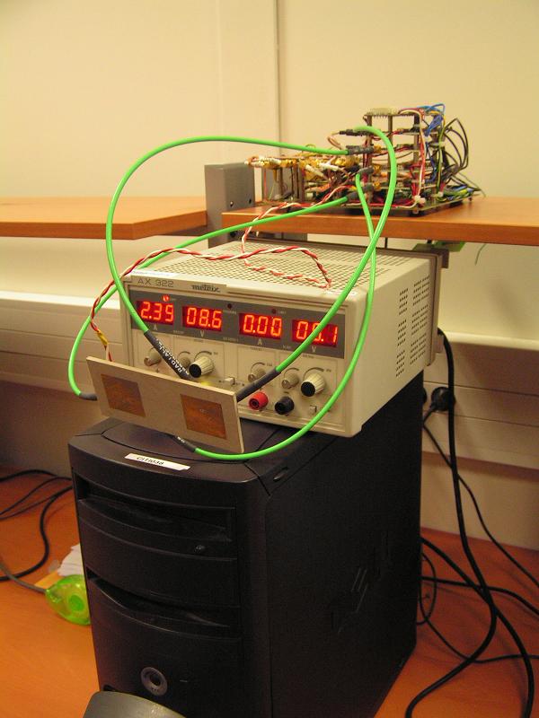
Combining multi-antenna, multi-channel and multi-standard principles in the same receiver seem to be a very promising issue to increase wireless transmission performances. However, several parameters like antenna coupling, channel correlation and also propagation channel properties have an important influence on SIMO performances. That is why a software demonstrator simulating the running of a 4 antennas receiver and able to deal with 802.11g/b signals in a 40 MHz bandwidth was developed using ADS software. Different SIMO algorithms, configurations of running (space between two interest communication channels), and propagation channel characteristics could be chosen to have a better estimation of the performances of our system in realistic working conditions. Moreover, thanks the compatibility with Agilent equipment, a complete multi-antenna (2x2) test bed radio platform was installed in order to rapidly test and evaluate performances of any stage of wireless transmission. Due to the current capacity of our platform, it is possible to record only 2 incoming signals simultaneous. However it is sufficient to introduce channel correlation and antenna coupling in our measure. That is why, even if the developed demonstrator is able to run with 4 receiving antennas, only 1x2 SIMO performances are presented. |

|
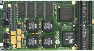
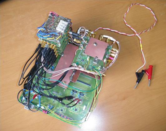
This parts describes different operating stage we develop in order to treat RF incoming signals to the BER of the transmission computation. A. RF stage A 2 patches antenna spaced by a distance of 6 cm and providing each 2 channels of orthogonal polarization is used. So, we have 4 incoming signals to treat. This antenna is designed for 2.4 GHz transmissions, and connected to the RF stage which allows the down conversion, and also an 80 MHz sampling and a 10 bits coding of the complex signal. B. Numerical Processing The numerical processing is computed using two TS-C43 PMC from VSystems. Each board comprises 4 clustered TigerSHARC DSP allowing a 300 MHz processing, a Xilinx Virtex-II FPGA and a 528 Mo/s PCI connection.
The TS-C43 PMC board FPGA and the RF stage are connected together by an external I/O connection of 100 pins, each one allowing a 100 MHz connection. Between FPGA and DSP, a 150 Mo/s connection is possible. However, rate of the incoming data from the RF stage to the FPGA, due to the sampling and the bit coding is 800 Mo/s. An important data rate decreasing must be applied in the FPGA. Part D will describe functions of different numerical processing components. At the end, each DSP is connected to a 600 Mo/s internal bus to access to SDRAM, Flash Memory and also the PCI gateway. Finally, the coding rate used with this TS-C43 board is 8 bits.
|
|
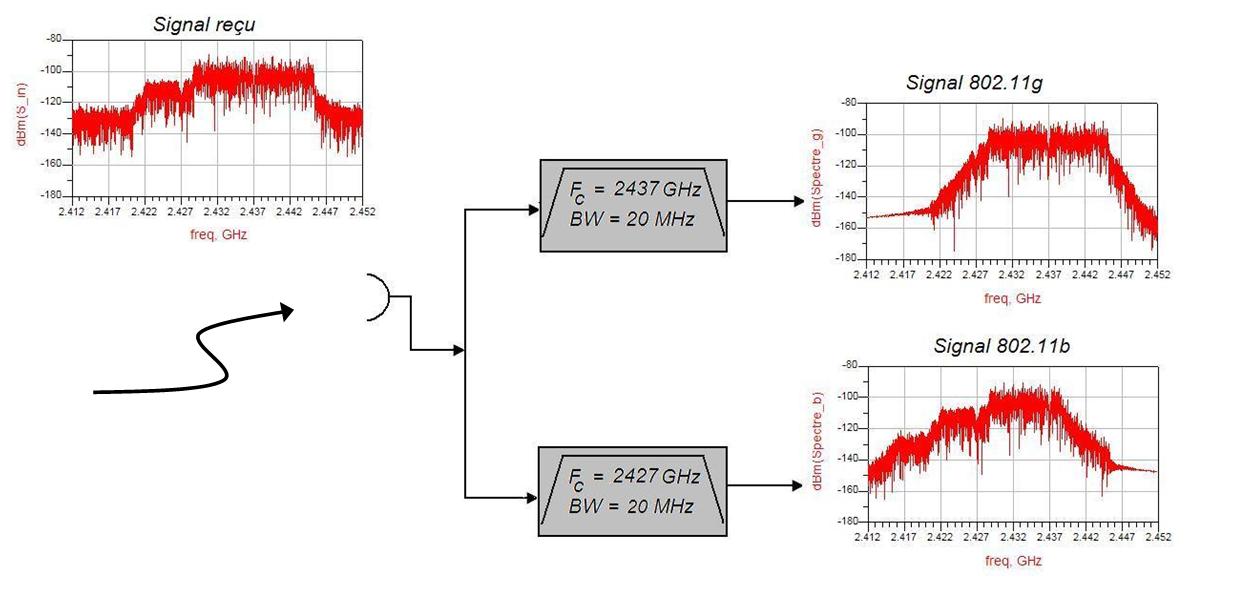
C. PC connection Thanks the 528 Mo/s PCI connection, numerical data are send to a dual-processor 3 GHz PC with a 4 Go RAM running Linux. The PC is used to combine the 4 numerical channels using different SIMO processing, and also to demodulate signals in order to compute BER of the transmission. At this stage of treatment, real time processing is not a really important parameter. Let us now list the most important functions used in the numerical processing stage. D. Numerical functions Each TS-C43 board has to deal with 2 reception channels. Remembering that our receiver must be able to deal with 2 802.11 communications at the same time, one DSP has to permit the global signal processing for 1 incoming signal. The major aim of the FPGA is to ensure an important data rate decreasing to make transmission to DSP possible. That is why the FPGA has to detect signal presence in the 40 MHz bandwidth of interest, detect the WLAN channel (carrier frequency) used and apply a 11 MHz filter around this carrier frequency on both complex channels (I and Q), which corresponds to a 22 MHz channel bandwidth. That way, the data rate is 44 Mo/s and there is no problem for transmission to the DSP. After a standard characterization and an adapted sampling according to the detected standard, numerical processing is applied to the signal.
Description of numerical functions
The above figure describes the different numerical functions implemented on each one of eight DSP. The Channel Impulse Response (CIR) for 802.11g transmissions is computed in frequency domain by the PC, before SIMO processing. In the case of 802.11b transmission, barker dispreading is applied after the optimal SIMO coefficients computation. Thanks the several algorithms implemented, the data rate in the PCI transmission to PC is sufficient low. At this time 802.11b and 802.11g processing have been tested with Matlab and implemented and tested with VC++ software. 802.11b receiver architecture is implemented on DSP and validated, but a lot work taking into account real time constraint has to be done.
|
|
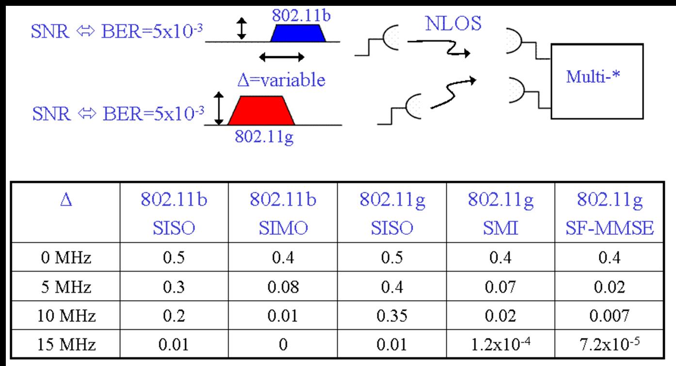
This table presents BER values in the case of the terminal is dealing with two recorded signals of each standard after propagation under a measured multi-path channel. Both signals are emitted to a sufficient level to guaranty no transmission error in the case of a mono standard communication. |